This section shows some examples in Python that use the RoboDK API. Most of these examples can be easily ported to other programming languages (such as C#, C++, .Net or Matlab). These examples were tested using Python 3 and might require some adjustments to work on Python 2.
Additional RoboDK API examples are included in the following folders:
Any Python files available in the Scripts folder can be run as a standalone script by selecting:
Some examples are used in sample RoboDK projects (RDK files) provided in the RoboDK library. Some examples are also available on GitHub: https://github.com/RoboDK/RoboDK-API/tree/master/Python/Examples.
This example shows how to generate a hexagonal path given one target. This macro draws a polygon of radius R and n_sides vertices using the RoboDK API for Python.
6.2. Offline Programming (GUI)
This example is an improved version of the previous example. It prompts the user for some input before simulating or generating a program. This example shows how RoboDK and the Python GUI tkinter can display graphical user interface to customize program generation according to certain parameters.
6.3. Online Programming
This example is a modified version of the previous two examples which supports running the program on the robot directly from the script. This example will run a Python program on the robot from the Python API (online programming). If a robot is connected to the PC, the simulation and the real robot will move at the same time as the Python program is executed. The same program can also be used for simulation or offline programming.
This example shows different ways of moving a robot along a list of points.
Move robot through points ¶ to automatically follow the curve 6.5. Points to Curve
This example shows how to automatically setup a curve follow project from the API. This example achieves the same goal as the previous example in a different way by setting up a curve follow project or a point follow project.
Curve Follow Project ¶ to automatically follow the curve 6.6. CSV file to Program (XYZ)
This example shows how to import targets from a CSV file given a list of XYZ coordinates. Optionally, the 4th column will update the speed in the program.
This example is available as a RoboDK script by default:
6.7. CSV file to Program (XYZWPR)
This example shows how to import targets from a CSV file given a list of XYZWPR coordinates (poses).
6.8. Load a KUKA SRC file
This example shows how to import a KUKA SRC file as a robot program. Make sure to first load your KUKA robot in RoboDK (the one used for the SRC program), then, run this script using Tools -> Run-Script.
Load KUKA SRC Program ¶ C_DIS 6.9. Test Move Feasibility
This example creates a program that safely moves the robot through a set of points checking that linear movements can be achieved (including collision checking or not). The points are automatically created as a cube grid around a reference target. If a linear movement can’t be achieved from one point to the next the robot will try a joint movement if a joint movement is also not possible the point will be skipped.
Test MoveL and MoveJ ¶ 6.10. Docked UI
This example shows how to embed a window in RoboDK. In this case a GUI window created with TKInter is added as a docked window in RoboDK.
Docked window ¶ 6.11. Estimated cycle time
This example shows how to calculate estimated cycle times.
Cycle time ¶ " 6.12. Change tool
This macro allows updating the tool given an ID that is passed as an argument for robot machining purposes. If no ID is passed as argument it will pop up a message. This macro can be used together with a robot machining project to change the tool as it simulates. Double click your robot machining project, select Program Events, and enter SetTool(%1) for a tool change event.
Set milling tool ¶ 6.13. Project curve to surface
This example projects the features (points/curves) to a surface and calculates the normals to the surface. This example takes 2 objects: (1) an object with curves and/or points and (2) an object with one or more surfaces.
Project curve to surface ¶ type of projection 6.14. Filter curve normals
This macro shows how to average the normals of an object containing curves. This macro can also filter points that are too close to each other. The user must select an object, then, a copy of this object is created with the averaged normals.
Filter curve normals ¶ = 1" 6.15. Change curve normals
This example shows how to change the curve normal of an object to point in the +Z direction by changing the i, j and k vectors to (0,0,1).
Change curve normals ¶ 6.16. Attach object to a robot link
This example shows how to attach an object to a robot link. Once you place the object at the preferred position, you can run the script in your RoboDK station.
Attach object to a robot link ¶This example shows how to move the robot using the keyboard. This macro needs to be executed as a separate process to properly intercept the keyboard (not within RoboDK). This example could be extended to move the robot using an Xbox controller, a Wii Remote or any other input device.
Move a robot using the Keyboard ¶ 6.18. Connect to Robots
This example shows how to connect to all robots available in the RoboDK station using robot drivers and move the robot to the positions set in RoboDK. This example shows how to communicate with more than one robot at the same time.
6.19. Monitor Joints
This example shows how to save the simulated position of a robot to a text or CSV file.
Monitor simulated joints ¶ 6.20. Monitor a Real UR robot
This example shows how to monitor a Universal Robot connected to a PC. Among other things, the position of the robot, speed and acceleration can be monitored at 125 Hz.
6.21. Pick and Place
This example shows an advanced pick and place application using a Fanuc M-710iC/50 robot (Example 2 from the RoboDK library).
In this example all the robot movements of the Fanuc robot are managed by the Python program. Using the Python API it is possible to create, move, modify and delete any object, reference frame, robot or other items in the station.
Example 02-1 - Pick and place with python ¶ nTCPs) 6.22. Update Machining Tools
This script will update all tools that have a Length flag in the tool name (Example: Tool L220.551) with respect to a reference tool. The reference tool must have a reference Length (example: Calib Point L164.033). This is useful to specify a standoff or define a specific milling tool with respect to a reference tool.
Update robot machining tools ¶ 6.23. Project TCP to Axis
This script projects a tool (TCP) to an axis defined by two other calibrated tools (two TCP that define an axis). This script also aligns the tool orientation (axis Z) to match the calibrated axis. A popup will be displayed to provide the tool errors before you update the TCP.
This script is useful if the point and axis of a spindle needs to be accurately calculated (for example, for robot machining or cutting).
Tool (TCP) to axis projection ¶ 6.24. Robot Machining Settings
This example shows how to modify settings related to robot machining and program events using the RoboDK API.
Double click a robot machining project, curve follow project, point follow project or 3D printing project to see the settings.
Select Program Events to see the events.
Next section shows how to change the axes optimization settings (may be needed when a robot is combined with external axes).
The variables can be retrieved or set as a dict or JSON string using the parameter/command Machining and ProgEvents as shown in the following example.
Update robot machining settings ¶ 6.25. Axes Optimization Settings
This example shows how to read or modify the Axes Optimization settings using the RoboDK API and a JSON string. You can select “Axes optimization” in a robot machining menu or the robot parameters to view the axes optimization settings. It is possible to update the axes optimization settings attached to a robot or a robot machining project manually or using the API.
The variables can be retrieved or set as a dict or JSON string using the parameter/command OptimAxes as shown in the following example.
Update axes optimization settings ¶ 6.26. Modify Program Instructions
This example shows how to modify program instructions.
This example iterates over the selected program changing the speeds, and removing any pause instructions and adding custom program calls.
Modify program instructions ¶ 6.27. Drawing an SVG image
A robot is programmed given an SVG image to simulate a drawing application. An ABB IRB 4600-20/2.50 is used in this example.
Example 03 - Drawing with a robot ¶ 6.28. Synchronize 3 Robots
This example shows to synchronize multiple robots at the same time. The robots can be synchronized together given keypoints and using Python threads. This example is similar to Offline Programming but updated to support moving multiple robots at the same time. The robots can be connected to the computer using appropriate robot drivers and switch from the simulation to moving the real robots.
Offline programming - 3 robots simultaneously ¶ 6.29. Robot Model (DH)
This example models the forward and inverse kinematics of an ABB IRB 120 robot using the RoboDK API for Python. Reference frames are placed according to an existing robot in the station.
Robot Model - Mirror test ¶ 6.30. Camera (2D)
This example demonstrates some of the basic functionalities to manage 2D cameras using the RoboDK API for Python. It creates or reuse an existing camera, set its parameters, get the image using two different methods and display it to the user as a live stream. This is a great starting point for your computer vision algorithms.
Camera Live Stream ¶ 6.30.2. Camera calibration
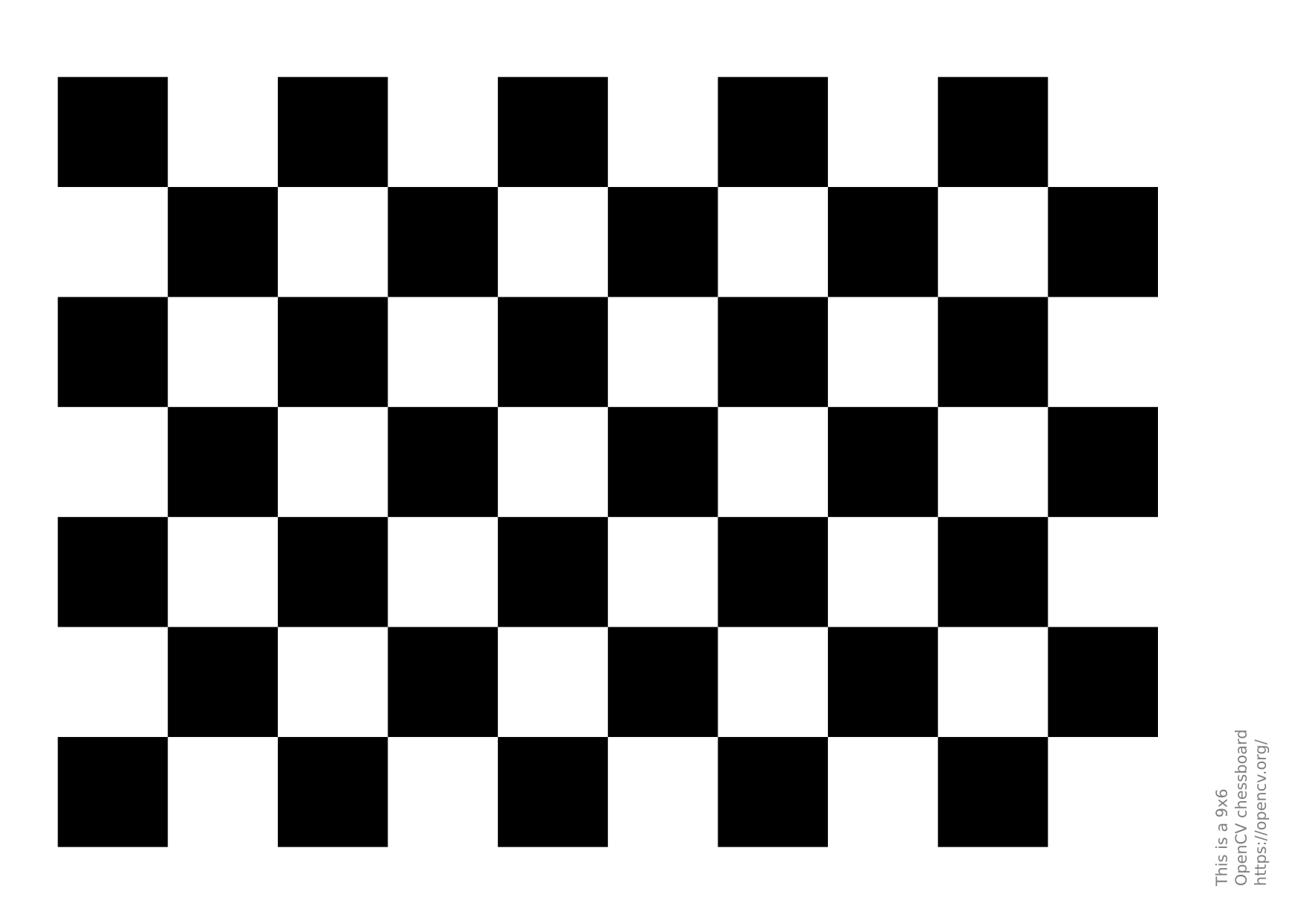
This example shows how to find a camera intrinsic properties using OpenCV. Print the chessboard and take a series of at least 5 images while moving the chessboard around. You can find more information in this OpenCV calibration tutorial.
6.30.3. Camera hand-eye calibration
Hand-eye calibration is the process of determining the camera “eye” position with respect to the robot flange or tool using OpenCV. The scripts provided in this example will help you collect the required data to perform hand-eye calibration. You will need a chessboard (checkerboard) or charucoboard to perform the calibration.
Although the tools provided are for online programming (the camera and the robot are connected to your computer and accessed by RoboDK), you can still adapt these scripts to perform it offline.
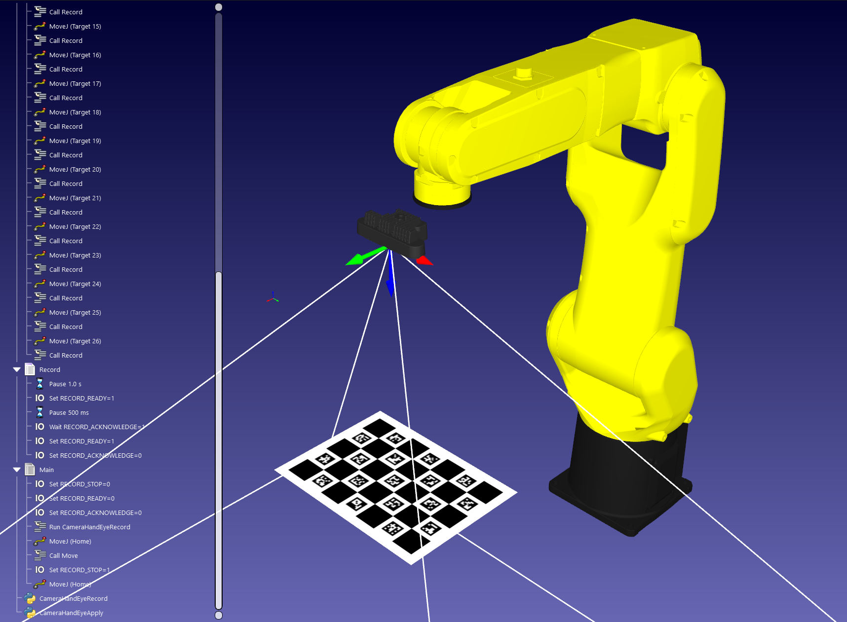
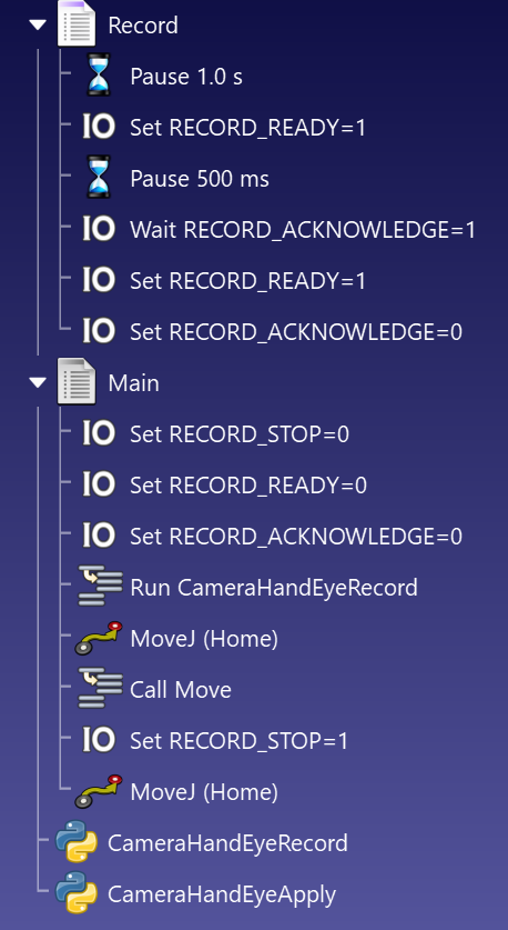
The first script is the acquisition script. Add it to your RoboDK station and launch it from your main program in a separate thread. Using IOs, you can trigger the recording of the robot pose and the camera (see the image below). Robot poses and images are saved on disk as JSON and PNG files with a matching ID. If you use another camera system, you can disable the camera acquisition and only record the robot poses.
The second script is the hand-eye calibration script. You can run it separately in your IDE or by adding it to your station. A dialog will open to retrieve the images and robot poses acquired by the previous script. The hand-eye calibration can then by applied to the selected tool (we recommend applying the hand-eye calibration to a new tool). Note that this is for eye-in-hand calibration (robot is holding the camera), but it can be easily adapted for eye-to-hand (static camera pointing to the robot).
OpenCV - Hand-Eye calibration 
) that contains the rotation, (3x3) rotation matrices or (3x1) rotation vectors, for all the transformations from gripper frame to robot base frame. ) that contains the (3x1) translation vectors for all the transformations from gripper frame to robot base frame. ) that contains the rotation, (3x3) rotation matrices or (3x1) rotation vectors, for all the transformations from calibration target frame to camera frame. ) that contains the (3x1) translation vectors for all the transformations from calibration target frame to camera frame. save images with OpenCV using cv.imread(filename) and cv.imwrite(filename, img))) 6.30.4. Camera pose
This example shows how to estimate a camera pose in real-time using OpenCV. You need a calibrated camera to estimate the camera pose, see the previous example. You can find more information in the OpenCV ChArUco tutorial.
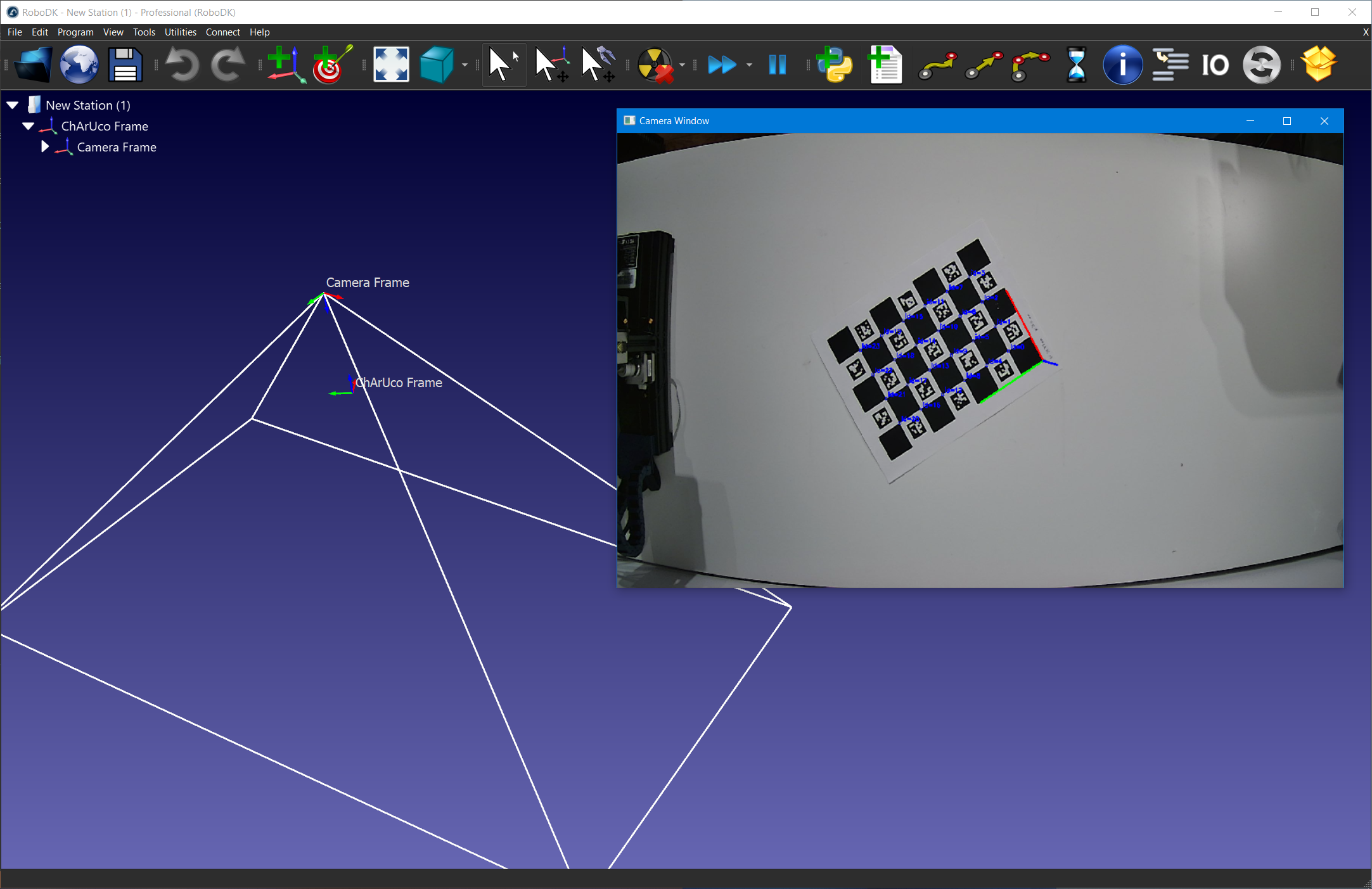
Print the charucoboard in letter format and place it in front of the camera.
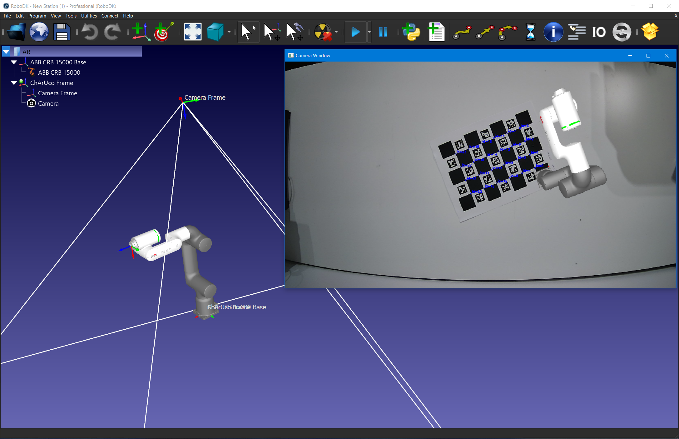
6.30.5. Augmented Reality
This example shows how to apply augmented reality from RoboDK to on a input camera feed using OpenCV. You need a calibrated camera to estimate the camera pose, see the previous example.
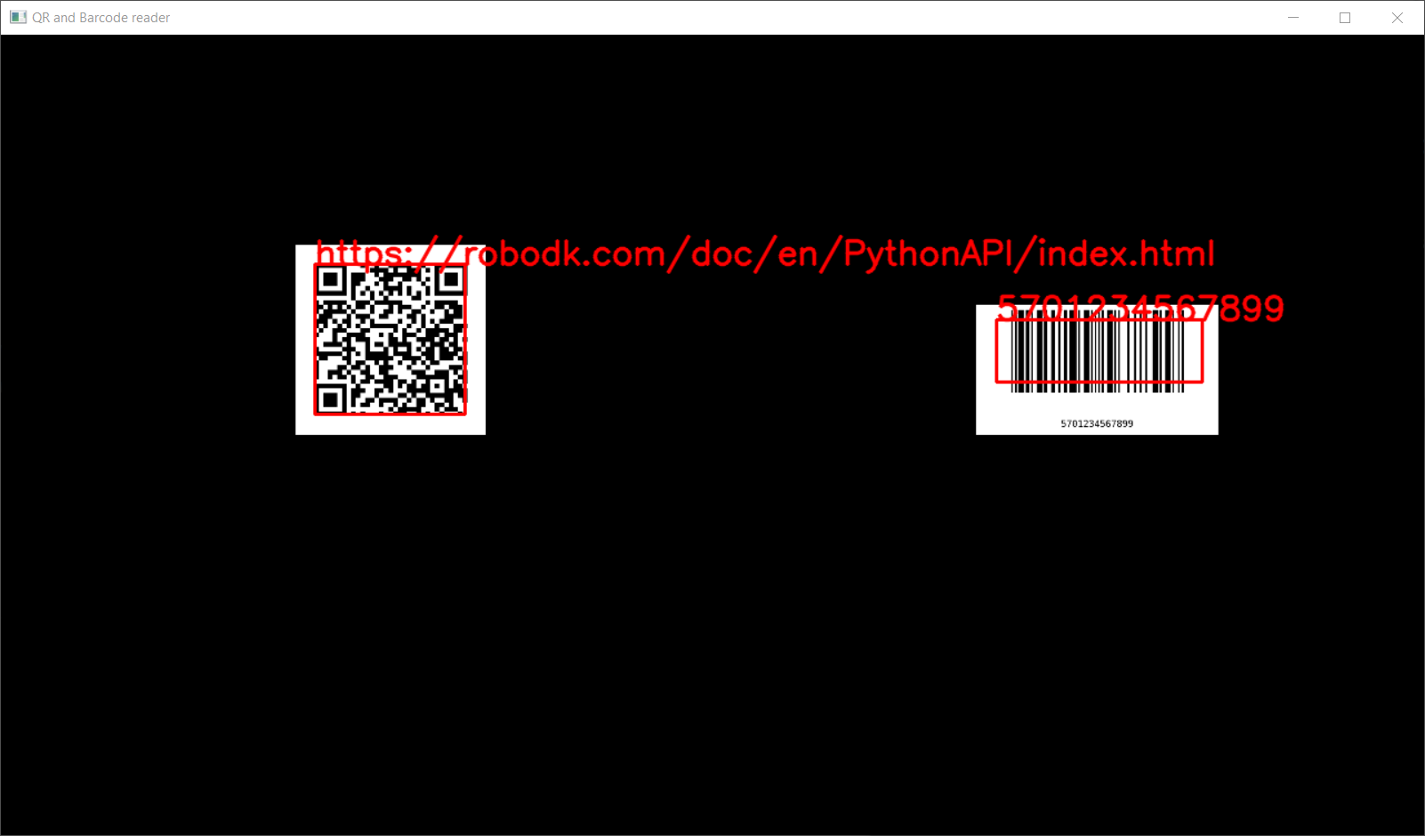
6.30.6. QR codes and barcodes
This example shows how to read QR codes and barcodes (EAN-13, UPC-A, etc) from an input camera in RoboDK. The input camera can be a physical device or a simulated camera from RoboDK. It also provides utility scripts to add QR codes and barcodes as objects to a RoboDK station.
Detected QR code and barcodes will be shown in a separate view window, with detection highlighted in red. After detection, you can request the robot to place the item on a specific conveyor, bin, etc. based on the readings.
6.30.6.2. Generating barcodes (EAN-13)
Barcode (EAN-13) - Generator 
6.30.6.3. Reading QR codes and bar codes
QR and barcode - Reader 
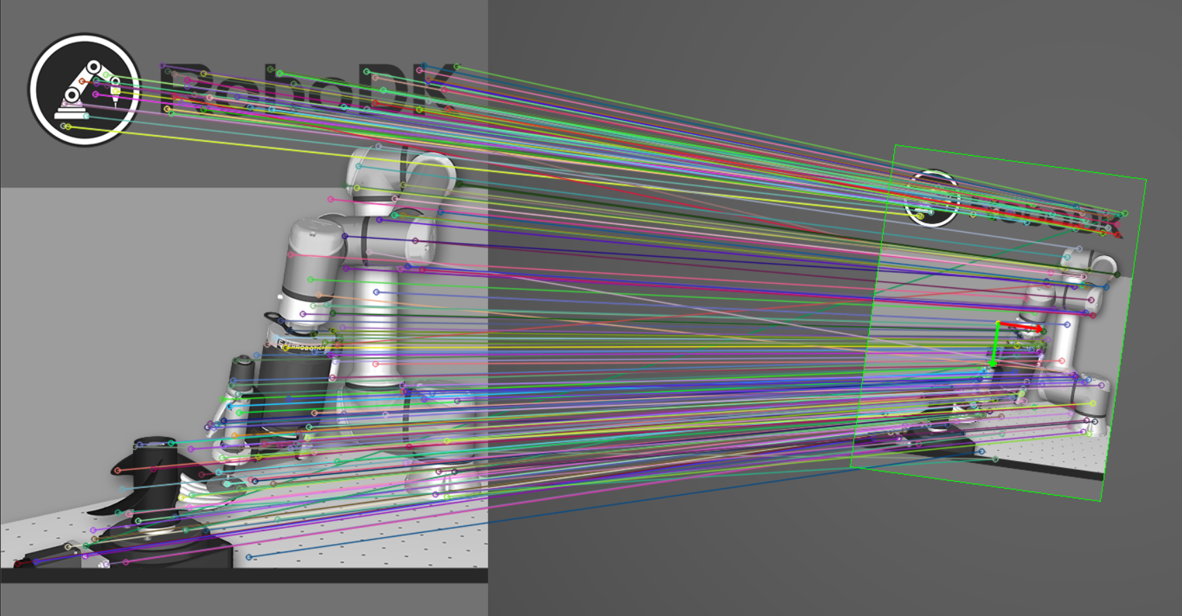
6.30.7. Object detection
This example shows how to match an input image (source object) with a camera feed to determine it’s 2D pose using OpenCV. It uses a simulated camera, but it can easily be modified to use an input camera. This only calculates the rotation along the Z axis, and the X/Y offsets. It is not meant for 3D positioning. You can find more information in the OpenCV homography tutorial.
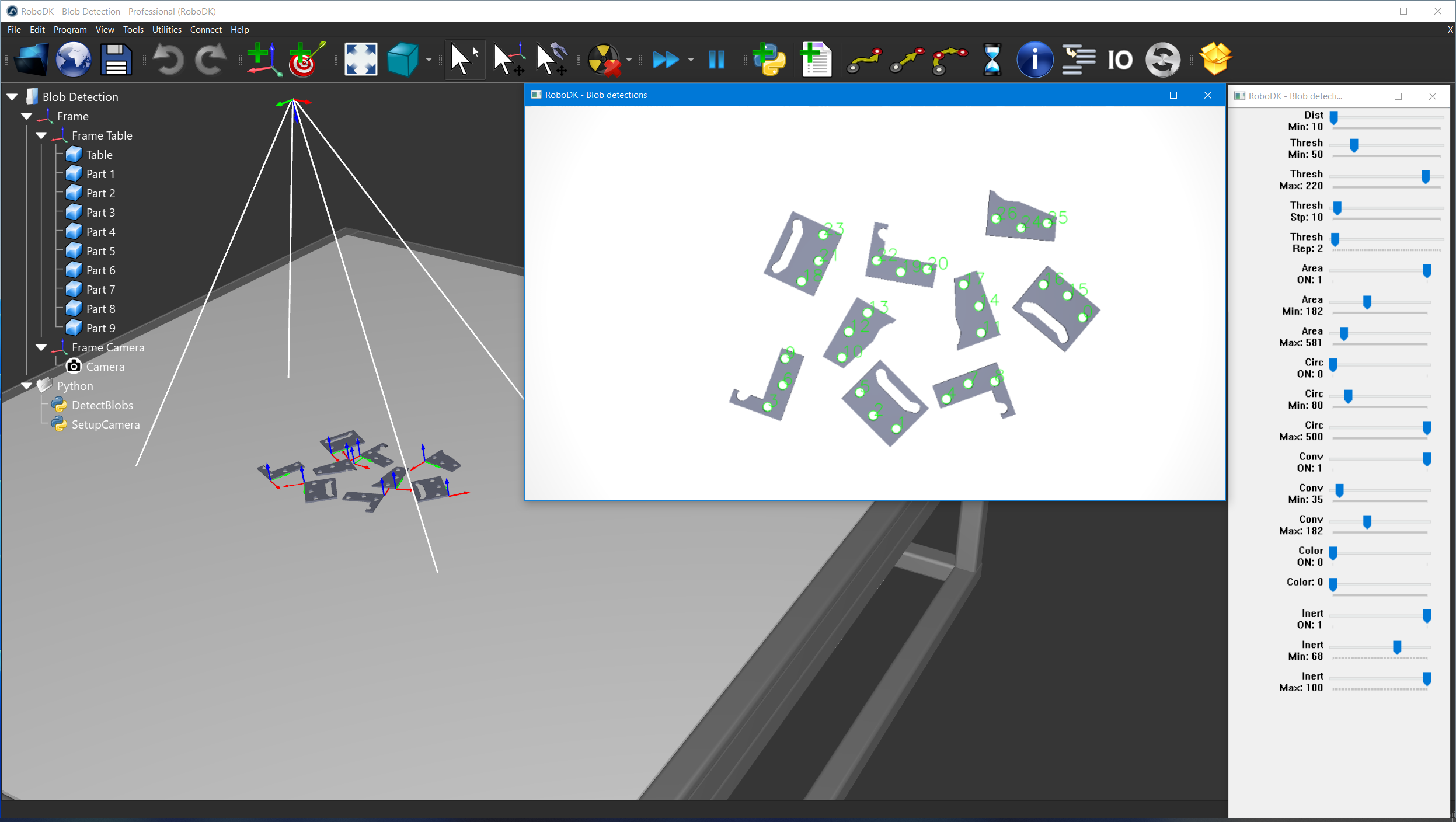
6.30.7.2. Blob detection
This example shows how to detect simple geometrical shapes (blobs) using OpenCV. It uses a simulated camera, but it can easily be modified to use an input camera. You can find more information in the OpenCV contours tutorial.
6.30.7.3. Orientation of elongated parts
This example shows how to detect the orientation of elongated parts in a camera feed using OpenCV. It uses a simulated camera, but it can easily be modified to use an input camera. You can find more information in the OpenCV contours tutorial.
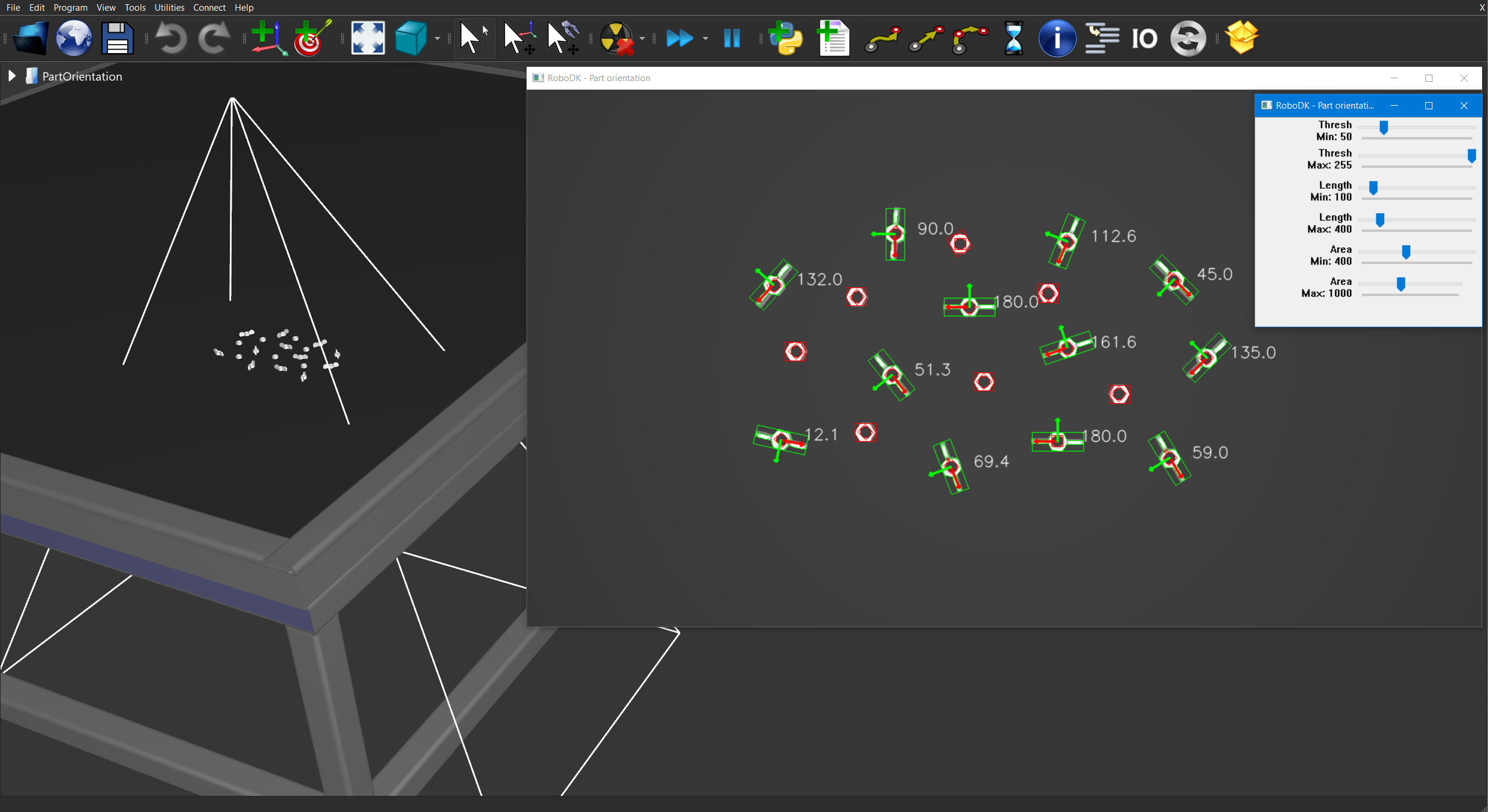
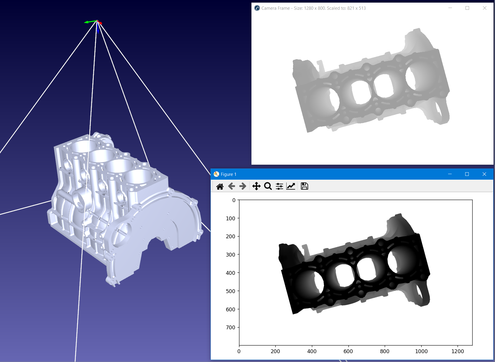
bottom left and bottom right edge of the box 4: pi: 6.31. Depth Camera (3D)
This example shows how to retrieve and display the 32-bit depth map of a simulated camera.
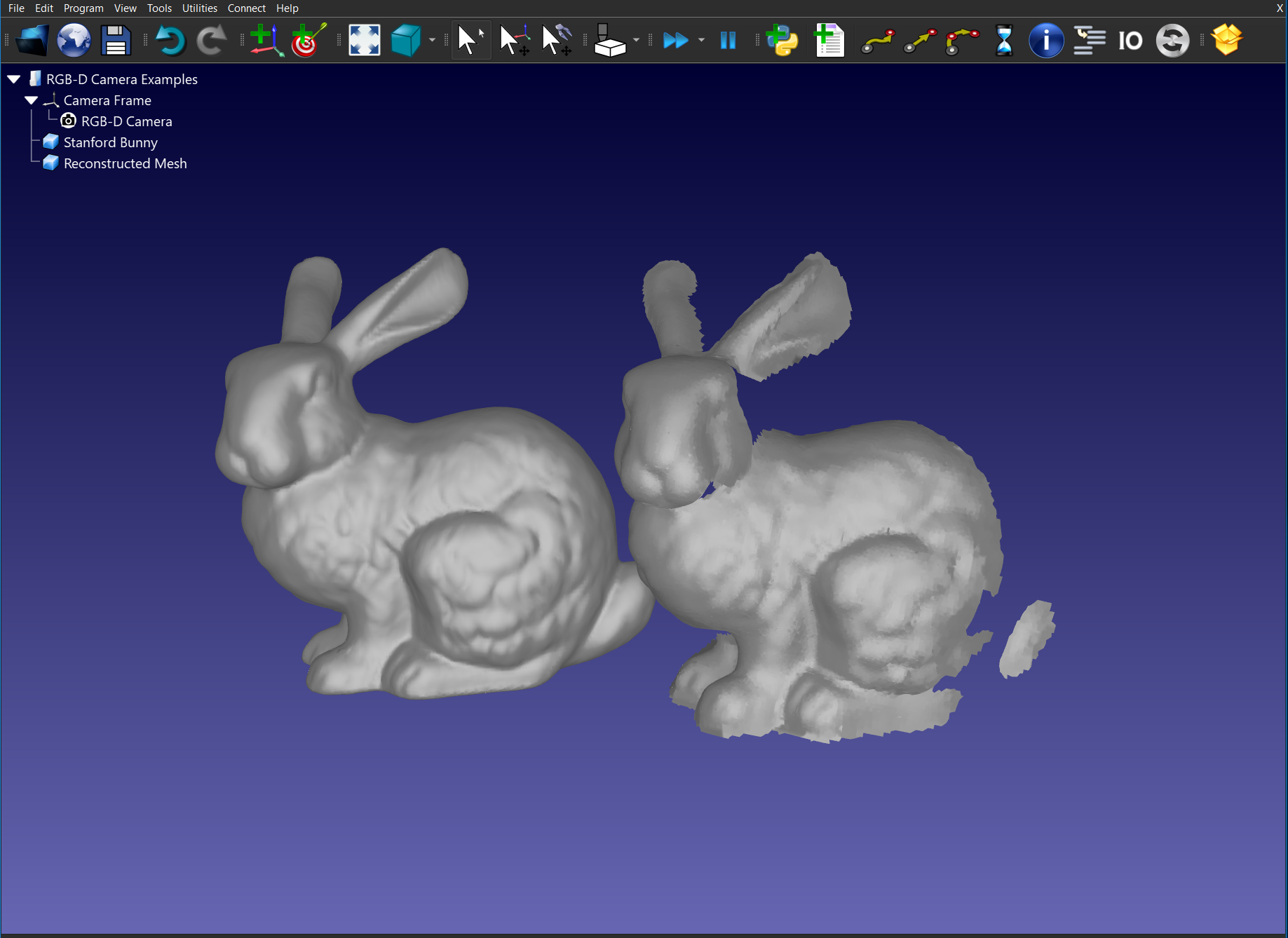
6.31.2. Mesh reconstruction
This example shows how to convert a depth map into a mesh object using Open3D. Using the Stanford Bunny and a RoboDK simulated camera, you can extract the 32-bit depth map, convert it into a point cloud, approximate a mesh, visualize it in a 3D Viewer and import the object back into RoboDK.
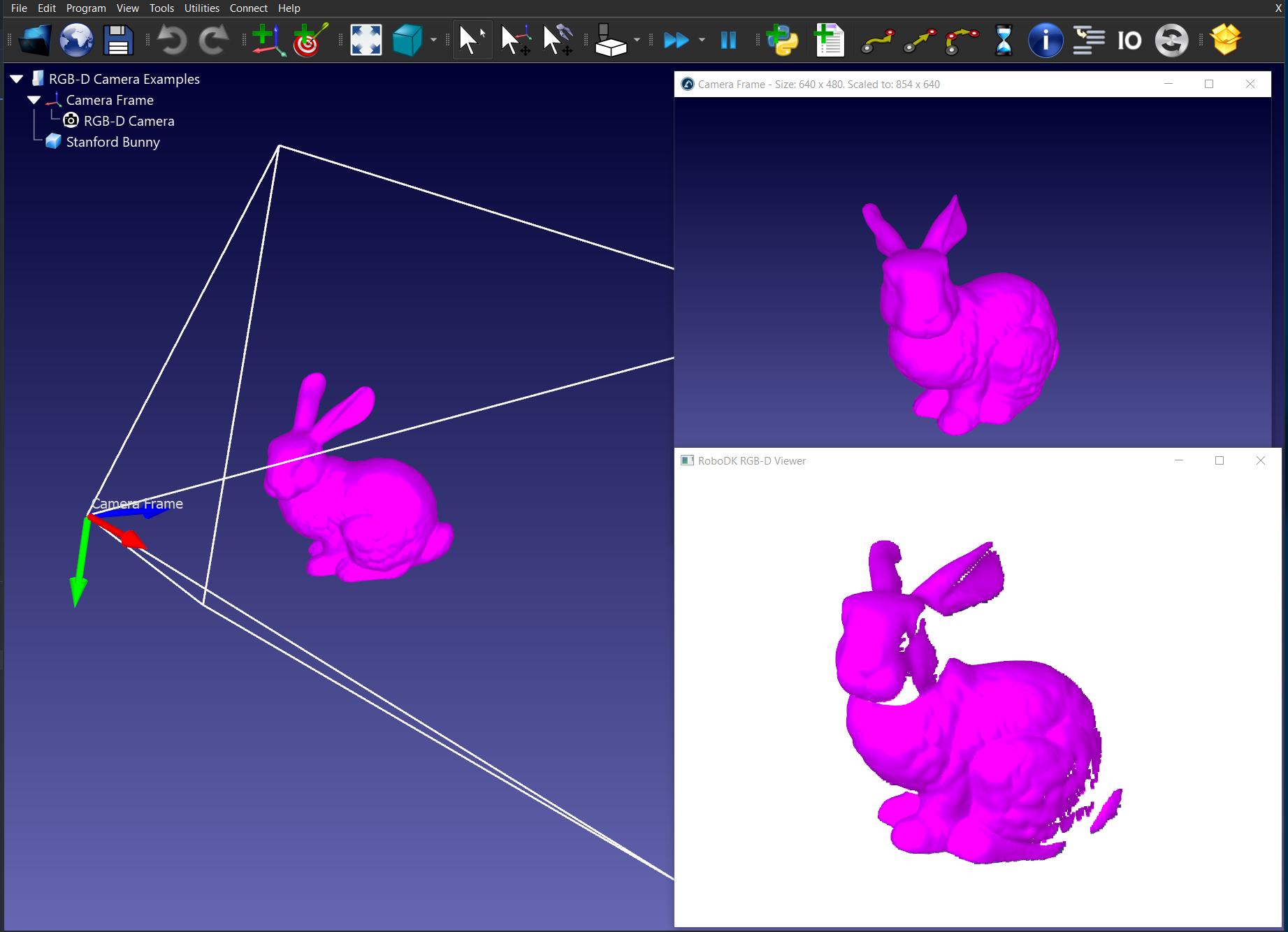
6.31.3. RGB-D Livestream
This example shows how to visualize a RGB-D camera in 3D using Open3D. Using the Stanford Bunny and a RoboDK simulated camera, you can extract the 32-bit depth map, convert it into a point cloud and visualize it in a 3D Viewer.
© Copyright 2015-2024, RoboDK.